The Flipchart Method of PCB Assembly
Production information for PCBs usually comes in the form of component
overlays (diagram showing location of components and their ID numbers) and component parts lists (part number with associated component ID). The component overlay and parts list can be used to generate a flip chart for use in PCB assembly to make the process easier, accurate and repeatable.
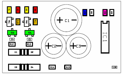
A flip chart is a collection of component overlays, with components highlighted to show where that component goes. Different types of component can have a different highlighter colour (probably max 6 colours) and so a number of different components can share the same page. Note: Each page has parts highlighted on it which are to be fitted in the same PCB orientation. Once the components on one page are fitted, turn (flip) to the next page, fit those parts, and so on until the PCB is fully populated.
Components are highlighted according to type and ID, and all components on one overlay will be fitted in the same orientation.
Under most circumstances, best practice would dictate that the PCB is turned to suit the orientation of the component, rather than the other way round, so it is important to work out which components would be fitted in which orientation, and therefore group them together on an overlay.
For an example and diagrams, download the pdf by clicking on the image below (640kb).
